Buttons Wiring:
The user interface on the controller can be accessed in Ruby using a USB keyboard, a rotary encoder, or using 4 push buttons for: Menu, Cancel, Up and Down. There are also some optional buttons, that enable auxiliary functions in Ruby like starting a video recording, taking a picture, changing OSD layouts, changing camera settings on the fly and more. They are not mandatory, but make life easier and the user experience more enjoyable.Note: The user interface can be accessed and used now also using a rotary encoder. Please see the Peripherals section to see how to setup a rotary encoder.
If you choose to use buttons for interface navigation, you need to wire the buttons as in the pictures below. There is a common rail to all buttons, connected to 3.3v, and one individual connection from each button to a GPIO pin on the Raspberry Pi/Radxa board:
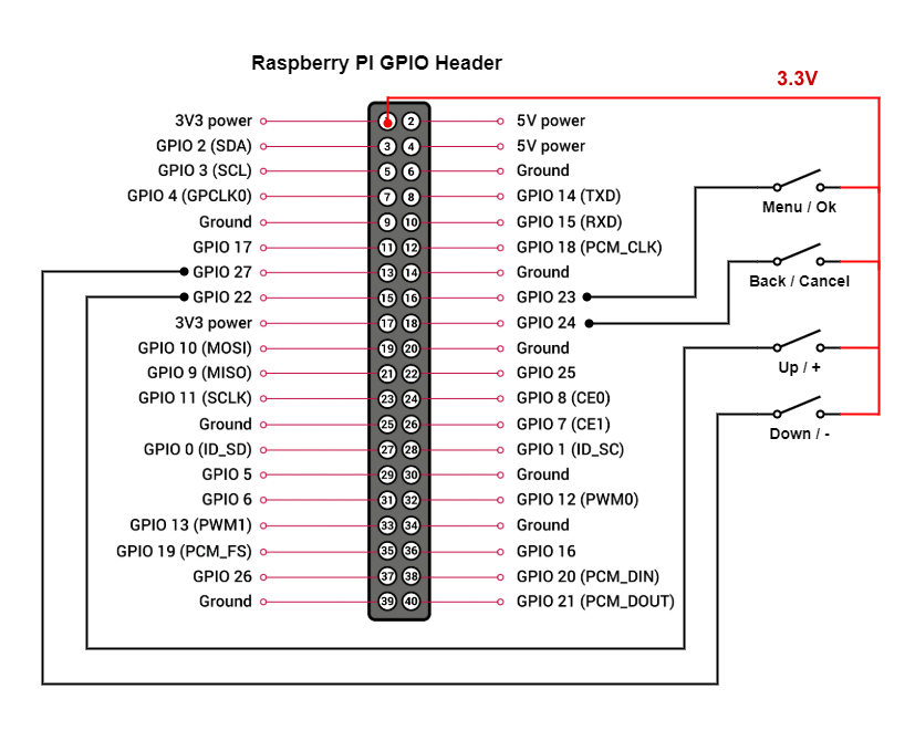
Menu Navigation Buttons Wiring for Raspberry Pi Boards
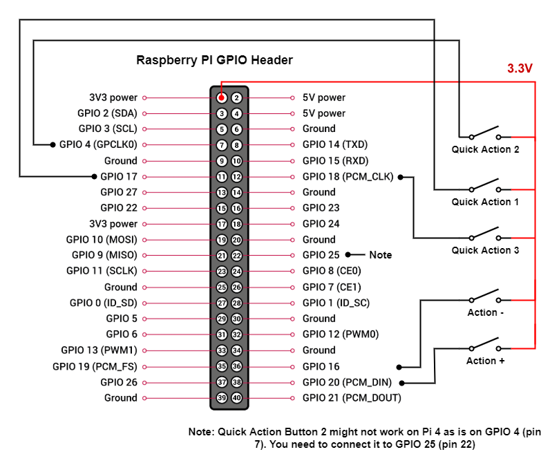
Optional Buttons Wiring for Raspberry Pi Boards
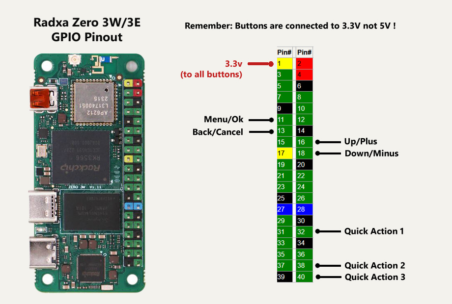
Menu and Optional Navigation Buttons Wiring for Radxa Zero 3 Boards
You can use different GPIO pins for menu navigation. To change the default assignment from the scheme above you need to:
- Insert the SD card (that has Ruby flashed on it) into a PC;
- On the partition that shows up, add a new file named gpio.txt;
- Edit this new file and add 4 numbers, corresponding to the GPIO pin numbers you want to use for Menu/Back/Up/Down;
- If you want to customize the GPIO pins for the Quick Actions too, add 3 additional numbers corresponding to the new GPIO pins to be used for QA1, QA2 and QA3;
- Save the file. That's all. Ruby will use the new GPIO mappings.
You can then assign what actions to do when pressing the Quick Actions buttons from the Preferences menu:
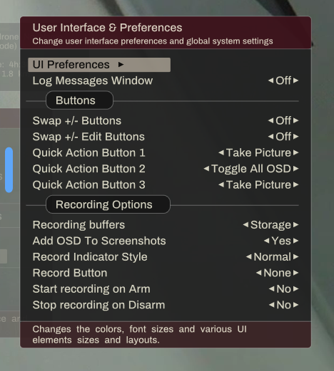
Quick Actions buttons
Other GPIO hardware connections:
There are few other hardware connections you can make to Ruby, that are optional, but can be used if needed.They are as follows (only for Raspberry Pi boards):
* A LED that will blink when video recording is turned on (on the controller side);
* A LED that will blink when there are major hardware or software issues (on the controller side);
* A GPIO pin (GPIO 19) that you can use to force a Pi to boot as a vehicle/relay, even if it has no camera (on the vehicle side);
* A GPIO pin (GPIO 26) that you can use to force a Pi to boot as a controller, even if a camera is present (on the controller itself);
The wiring for those is as in the picture below:
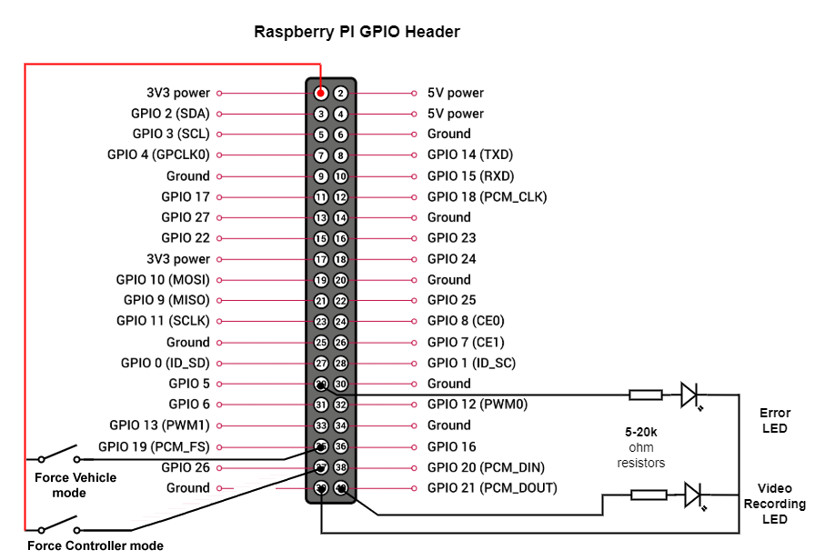
Optional LEDs and buttons