Hardware Setup
Here you find all the information on how to connect all the hardware components to create a Ruby system.
If you want to just buy ready to use Ruby systems, see our Store for links from where to Ruby systems from manufactured by different vendors.
Hardware Components:
Ruby supports a variety of hardware components in terms of cameras, radio modules, SBCs. Below is the minimum list of required components to create a fully working system.Note: You can mix and match hardware as needed. You don't have to use a single SBC across the board. That is, you can use different SBC for vehicles and controllers and use different radio modules on the same link (assuming they do support the frequency you will be using).
For example you can pair a Raspberry controller to an OpenIPC AIO unit. Or you can pair a Radxa controller to a Raspberry vehicle. All functionalities still work the same across the board, in whatever way you mix and match your hardware components.
Note! There are few exceptions to this rule due to the large hardware ecosystem and some software limitations on some hardware platforms. See Compatibility List for a complete list of exceptions and hardware compatibilities.
|
Controller
If you DIY, here is the list of components required to make a working controller:
|
Vehicles
If you DIY, here is the list of components required to make a working vehicle (drone, plane, car, UAV):
|
Here is the full list of supported hardware components:
Supported main boards
- RunCam VRx and air units;
- EMax VRx and air units;
- Pi Zero 2 (W);
- Pi 2,3,4 and variants;
- Radxa 3W/3E; Radxa 3C
- OpenIPC air units (AIO air units, Thinker, Sigmastar SSC338Q)
Relative performance of SBC/AIO units:
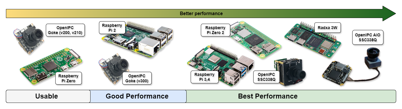
SBC/AIO Units Relative Performance
Advantages of using OpenIPC, RunCam, EMax air units on vehicles:
- Better video quality than most Raspberry Pi cameras. All OpenIPC hardware is using Sony IMX sensors which have great video quality and great low light handling; Same as Raspberry Pi HQ cameras and Veye cameras;
- Lower video feed glass-to-glass latency; As low as 40 ms (on current hardware);
- More compact. You don't need a SBC on your vehicle anymore as the air unit itself is a SBC;
Tip:
Ruby detects automatically, at boot time, if it's running on a vehicle/relay or on a controller. That is, the same firmware it's used on both sides. You don't need to configure it specially for each end.- A CSI or HDMI camera is present in the system and detected by Ruby;
- The GPIO pin 19 is detected as pulled-up (to 3.3V, only for Raspberry Pi boards);
- A file called forcevehicle or forcevehicle.txt is present to the SD card;
Supported radio modules
| 433 Mhz band | SiK, ELRS radio modules |
| 868/915 Mhz band | SiK, ELRS radio modules |
| 2.3/2.5 Ghz band | Atheros chipsets AR9271 cards: TPLink WN722N V1 |
| 2.4 Ghz band | Atheros chipsets AR9271 cards: TPLink WN722N V1, Alfa AWS036NHA Ralink chipsets cards: Alfa AWUS036NH |
| 5.8 Ghz band | Realtek chipsets RTL8812AU, RTL8811AU, RTL8812EU cards:
|
Note: These radio modules have been tested as working, but any radio modules with those chipsets will work just fine.
Note 2: Atheros radios are not recomended due to some limitations in the drivers. You can use them but you must accept the limitations (adaptive video will not work).
Relative performance of radio modules:
Note 2: Atheros radios are not recomended due to some limitations in the drivers. You can use them but you must accept the limitations (adaptive video will not work).
Relative performance of radio modules:
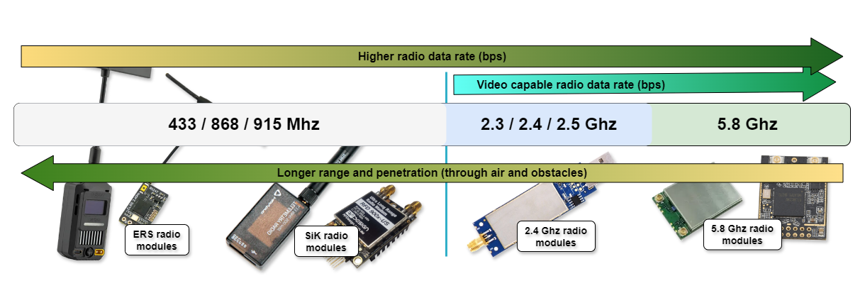
Radio Modules Relative Performance
Supported cameras
- Raspberry Pi v1,v2, HQ cameras *
* Most ArduCam cameras are not compatible. They are not supported on all Pi versions, have performance issues and/or lack control capabilities.
- Veye cameras 290/309/327 variants (http://www.veye.cc/en/);
- Any digital camera that has a HDMI output (720p or 1080p), using a HDMI-CSI adapter board;
- OpenIPC cameras; OpenIPC hardware (AIO air units, Sigmastar SSC338Q);
Recommended cameras:
Raspberry HQ;
Veye cameras;
OpenIPC AIO unit, OpenIPC Sigmastar SSC338Q;
Raspberry Pi v1 and OpenIPC Goke cameras are not supported anymore due low image quality and single core CPU;
Note: Raspberry Pi v3 cameras (or any camera that reqires libcamera support) are not supported. Check with your camera vendor/manufacturer to see if it requires libcamera support for it to work on Raspberry.
Tip:
All hardware components in Ruby are plug and play. So, when you add or remove hardware components, Ruby automatically configures them and the system to match the new hardware configuration. You can still configure the settings of each hardware component as needed.
Wiring and connections:
If you are new to electronics and DYI projects, it's recommended you start with the basic wiring and connections as in the pictures below as it's easier and faster to do and have a system up and running: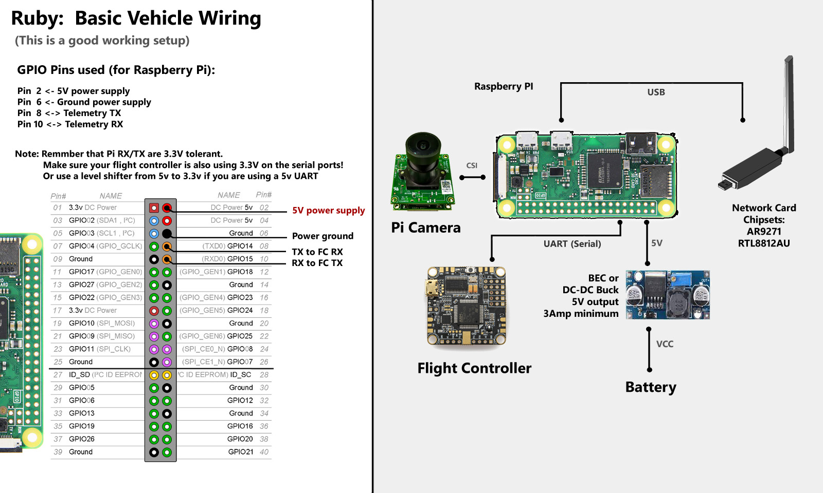
Basic vehicle wiring
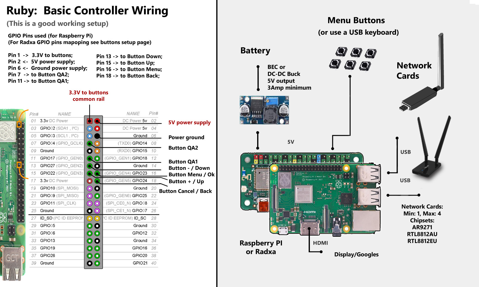
Basic controller wiring
Note! If you have critical usage scenarios or you plan to use Ruby in environments with vibrations, it is recommended to replace all USB cables and connectors with wires that are soldered to the boards at each end. This gives a more robust system in terms of reliability and resilience to vibrations:
Direct wiring of USB connections:
It is recommended that you wire directly the USB connections, from Pi/Radxa to the radio cards, to not use USB cables and connectors, to avoid vibration issues, using the points on the Pi board that give you direct access to the USB data lanes, as in the pictures below: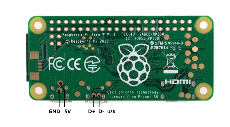
USB connection points for Pi Zero 2
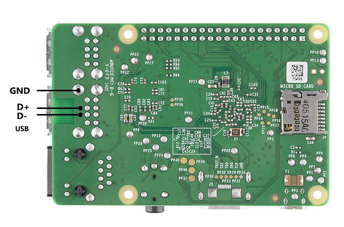
USB connection points for Pi 2,3 and variants
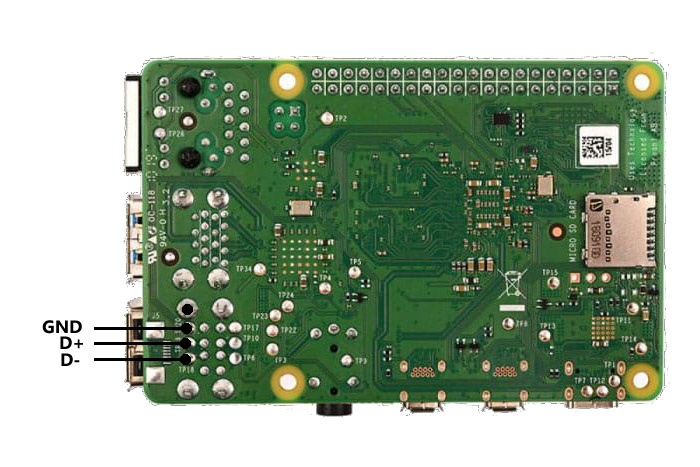
USB connection points for Pi 4 and Radxa 3C
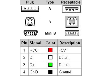
Different USB type connectors pinout
Note:On Radxa 3E/W, only one USB port can be used to connect radio interfaces to. The other USB port is not used.
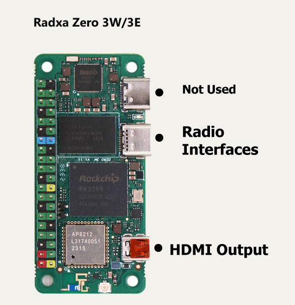
Radxa 3E/W UBS and HDMI usage
Note: On Raspberry Pi 4, the video output is generated on the HDMI Output Port 0. So you should connect a display to that port. The HDMI Output Port 1 is not used.
Buttons:
The user interface in Ruby can be accessed and navigated using a USB keyboard, a rotary encoder or push buttons. The more convenient way, long term, is to use push buttons for menu navigation. To do so, on the controller you need to add the 4 navigation buttons.No buttons, rotary encoders or USB keyboard are needed on vehicles.
Buttons Wiring:
The user interface on the controller can be accessed in Ruby (besides keyboard and rotary encoders) using 4 push buttons for: Menu, Cancel, Up and Down. There are also some optional buttons, that enable auxiliary functions in Ruby like starting a video recording, taking a picture, changing OSD layouts, changing camera settings on the fly and more. They are not mandatory, but make life easier and the user experience more enjoyable.Please see the Peripherals section to see how to setup a rotary encoder.
If you choose to use buttons for interface navigation, you need to wire the buttons as in the pictures below. There is a common rail to all buttons, connected to 3.3v, and one individual connection from each button to a GPIO pin on the Raspberry Pi/Radxa boards:
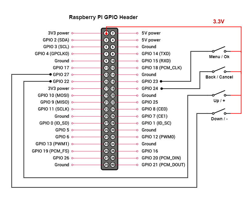
Menu Navigation Buttons Wiring for Raspberry Pi Boards
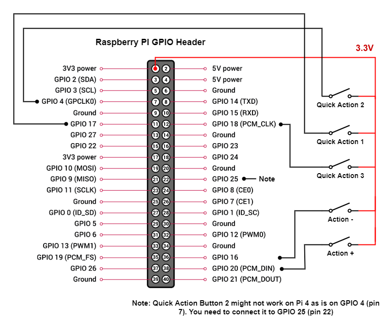
Optional Buttons Wiring for Raspberry Pi Boards
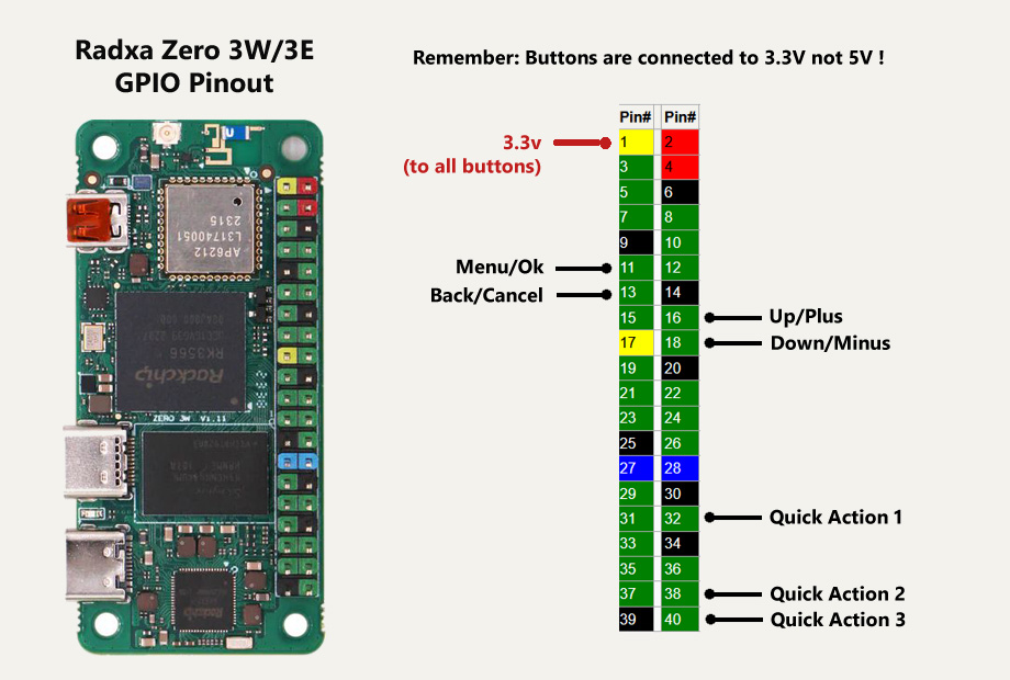
Menu and Optional Navigation Buttons Wiring for Radxa Zero 3E/W and Radxa 3C Boards
You can use different GPIO pins for menu navigation. To change the default assignment from the scheme above you need to:
- Insert the SD card (that has Ruby flashed on it) into a PC;
- On the partition that shows up, add a new file named gpio.txt;
- Edit this new file and add 4 numbers, corresponding to the GPIO pin numbers you want to use for Menu/Back/Up/Down;
- If you want to customize the GPIO pins for the Quick Actions too, add 3 additional numbers corresponding to the new GPIO pins to be used for QA1, QA2 and QA3;
- Save the file. That's all. Ruby will use the new GPIO mappings.
You can then assign what actions to do when pressing the Quick Actions buttons from the Preferences menu:
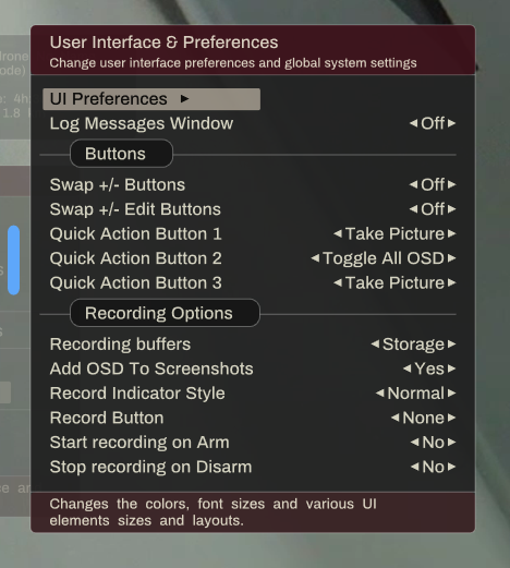
Quick Actions buttons
Other hardware connections:
There are few other hardware connections you can make to Ruby, that are optional, but can be used if needed.They are as follows (only for Raspberry Pi boards):
* A LED that will blink when video recording is turned on (on the controller side);
* A LED that will blink when there are major hardware or software issues (on the controller side);
* A GPIO pin (GPIO 19) that you can use to force a Pi to boot as a vehicle/relay, even if it has no camera (on the vehicle side);
* A GPIO pin (GPIO 26) that you can use to force a Pi to boot as a controller, even if a camera is detected (on the controller itself);
The wiring for those is as in the picture below:
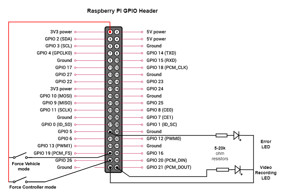
Optional LEDs and buttons
Serial Ports:
Ruby can communicate with external devices using serial interfaces (UART).The serial interfaces can be used to communicate with a flight controller, with a camera gimbal, a receiver or other devices based on each individual application.
If you need more than one serial interface, to connect to multiple devices, you can add any number of USB to serial adapters and connect them to the USB ports on the Pi, as in the picture below:
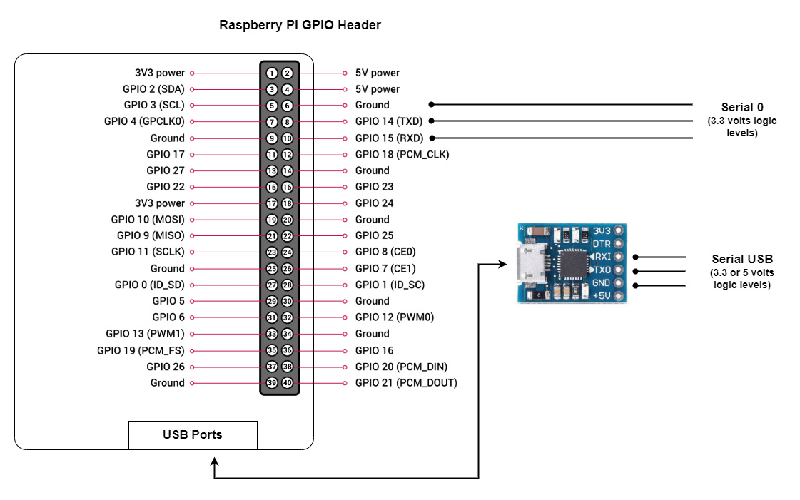
Accessing serial ports on a Raspberry Pi
Note: Use only brand name USB to serial adapters or ones with CP2109 or CP2102 chipsets. The USB serial adapters with CH340 chipset are not supported.
Note: The CP2102 chipsets are the most reliable ones and work in all conditions. The CP2109 might be incompatible with some Pi boards, depending on the manufacturer.
All available serial ports will be shown in the Ruby UI interface and you can change the parameters and usage for each individual port.
Most of the times, on the vehicle, you want to connect your flight controller to the Raspberry Pi so that Ruby can receive telemtry info from the flight controller and to send data and commands to the flight controller.
You need to connect the serial interface as in the picture below:
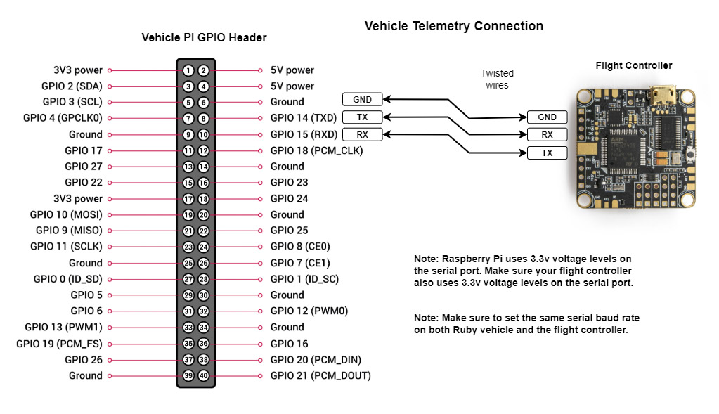
Wiring of flight controller for telemetry data
Note: Keep in mind that Raspberry Pi uses 3.3 volts logic levels. Most modern flight controllers (Pixhawk, Cube, STM32, etc) also use 3.3 volts so nothing special needs to be done. If you have an old or special flight controller that used 5 volts logic levels, you need to insert a level shifter.
Ruby Hardware Peripherals:
You can add optional hardware components to Ruby controller that will extend the functionality with new features.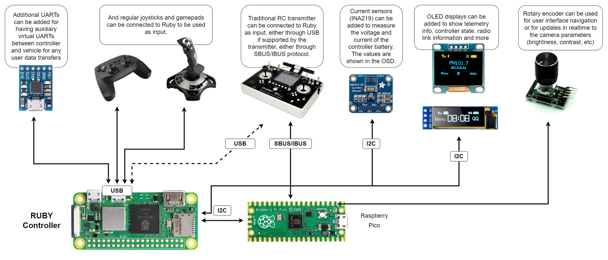
Optional peripherals that can be attached to the controller
Raspberry Pi Pico Add-on:
To expand the I/O capabilities of Raspberry Pi, to add more UART interfaces, analog inputs, SBUS/IBUS/PPM RC input and other future extensions, a small Raspberry Pi Pico is connected to the Pi controller using the I2C interface.The add-on Pico is powered directly from the main Pi:
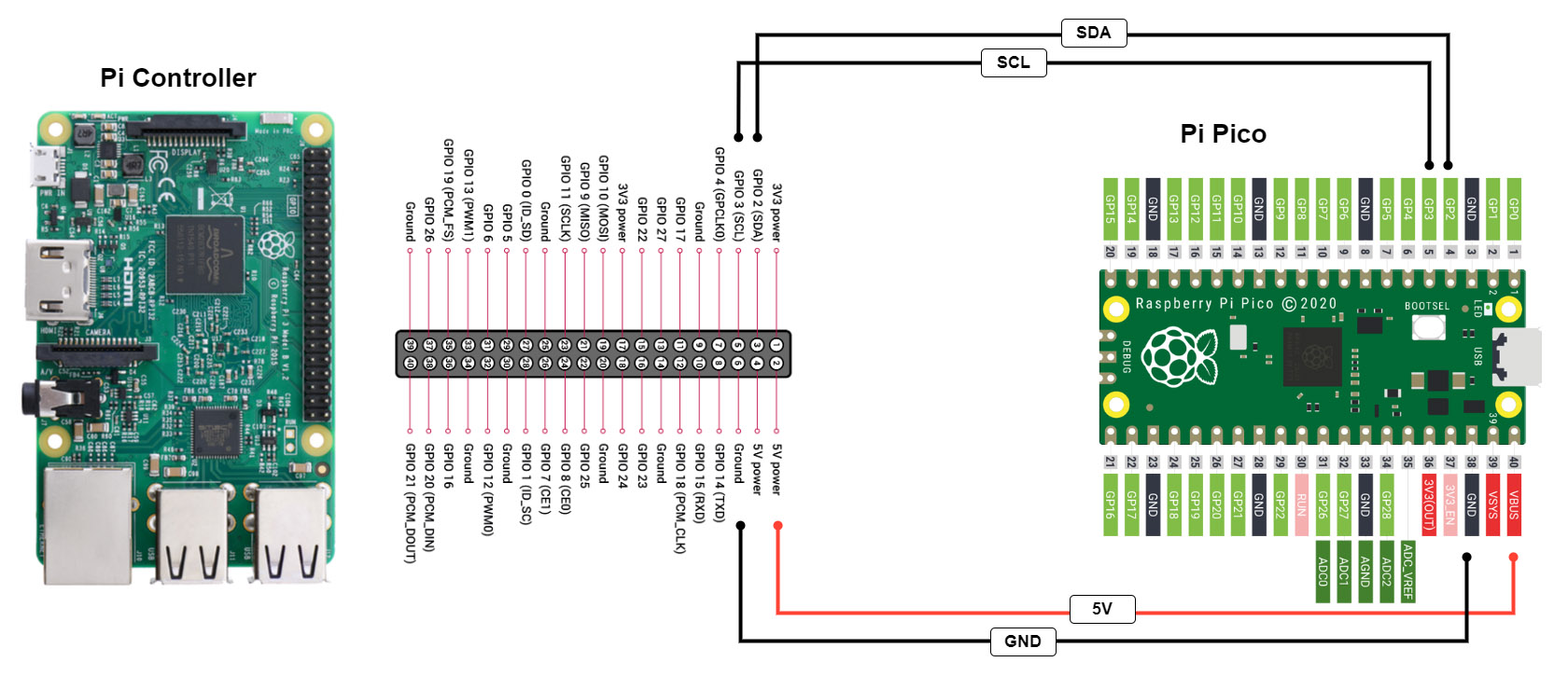
Connecting a Pico Pi to the controller Pi
To add peripherals to the Pico Pi, use the following diagram:
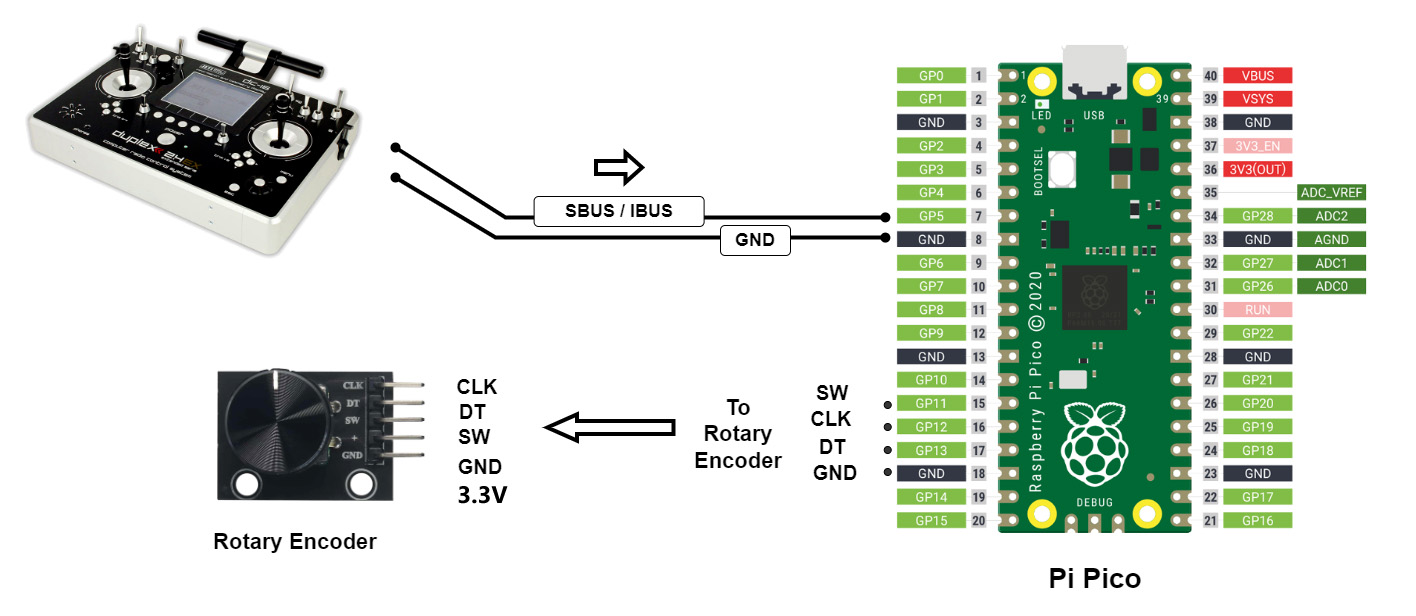
Connecting I/O peripherals to Pico Pi
You need to flash the Ruby software on your Pico. See the Downloads section for instructions on how to flash a Raspberry Pi Pico and to get the latest software for the Pico.
I2C Interface:
Ruby can use I2C interface and communicate with external devices.You can add multiple devices on the same I2C interface and all I2C devices that are detected at boot will show up in Ruby UI interface and you can change parameters for each individual I2C device.
Note: Raspberry Pi uses 3.3 volts logic levels. If you need to connect I2C devices that use 5 volts logic levels, use a level shifter as in the picture above.
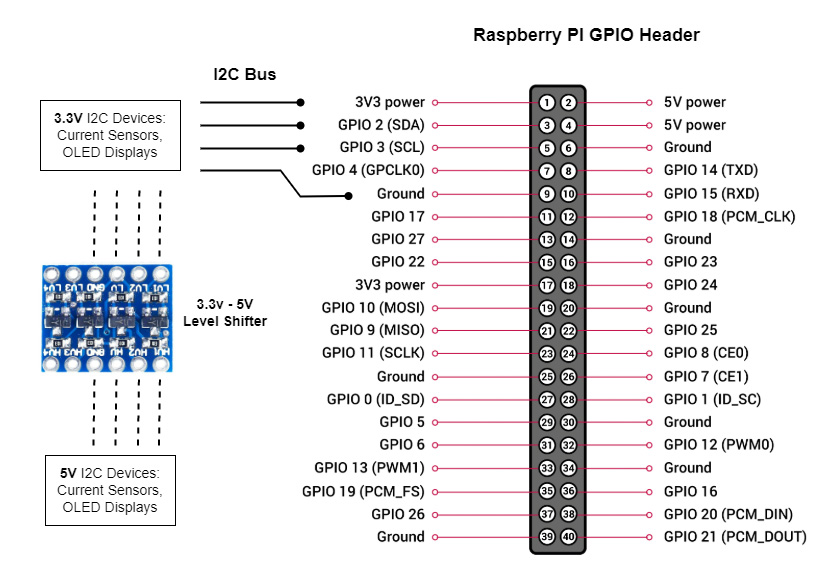
Using the I2C bus on the Raspberry Pi